Pages

Tuesday, December 27, 2016

4 Pin 7 Pin Trailer Wiring Diagram Light Plug


This article shows 4 ,7 pin trailer wiring diagram connector and step how to wire a trailer harness with color code ,there are some intricacies involved in wiring a trailer. Some trailers come with different connectors for cars and some have different wiring styles. If you follow our trailer wiring diagrams, you will get it right. Some connectors are 4-pin while some are 7-pin.

4 pin trailer light wiring diagram :

4-Pin Connectors

4-pin connectors are the standard used for most trailers. Many trailers have three circuits. The circuits are for left and right brake lights and running lights. Three wires are for the trailer while the last wire is the ground wire. The ground wire should be run from the frame of the vehicle to the trailer. There must be a very consistent metal to metal contact for the ground wire. So, do not run the wire from the bumper or the hitch of the car. The 4-pin standard flat style connector has four contacts with a male pin on the vehicle side for the ground.

Wiring the 4-pin connector

You will need a volt meter and a cutting plier to splice the wires. Turn on the running lamps of your vehicle. Probe the wiring to determine which of the wire that leads to the taillight is for the running lamp. Splice this wire and bring it to the vehicle end of the connector. The connection diagram below will tell you the exact place to place the wire. Repeat the process above for the left turn signal and the right turn signal lights

4 pin trailer plug  light wiring diagram color code

Thir is standard color code for a trailer light 4 wire :

  • Brown wire:  Tail light and marker light
  • Green wire :  Right Turn Signal
  • Yellow wire:  Lift Turn Signal
  • White wire :  Trailer Ground

7 pin trailer light wiring diagram :

7-Pin Connectors

7-pin connectors are needed because some trailers need extra connections due to the fact that they have multiple circuits. There are pins for electric trailer brakes, auxiliary power and reverse lights.

7 pin trailer plug  light wiring diagram color code

Thir is standard color code for a trailer light  7wire 
  • White wire :  Trailer Ground
  • Brown wire:  Tail light and marker light
  • Green wire :  Right Turn Signal
  • Yellow wire:  Lift Turn Signal
  • Blue wire    :  Trailer  Brake
  • red wire      : Auxiliary Power

Extra Notes

  • It is good to smear some dielectric grease on the connectors so that the pins will not be corroded by moisture.
  • Ensure everything is properly tightened and fixed so you do not have a loose connection. It will also save you the stress of troubleshooting later on.
Are You Interested in article :


Wednesday, December 21, 2016

How To Wire An Electrical Outlet Wiring Diagram


How to wire an electrical outlet wiring diagram ,Wiring an electrical outlet / receptacle is quite an easy job. If you are fixing more than one outlet, the wiring can be done in parallel or in series.

STEPS TO TAKE WHEN WIRING THE ELECTRICAL OUTLET/RECEPTACLE


how to wire Multiple electrical Outlet receptacle In Parallel serie  Wiring Diagram

How To Wire An Electrical Outlet :

  • Switch off the mains: You should switch off electrical power from the mains to avoid electrocution. One can’t be too careful. 
  • Run the cable from the circuit breaker to the location of the electrical outlet: Your cable should be long enough to reach each socket. The cable must also be strong enough to support the kind of load you want it to carry. 
  • Strip/peel off the cable before it enters the socket box: You can push in the cable to the box before screwing or nailing the box to the wall. Ensure the cable you feed in is long enough to reach the terminals of the socket. 
  • Connect the wires to the receptacles: The neutral, earth and live wire should be connected to the box. The earth wire is usually green/yellow while the live is usually pink/red. The neutral could be white or black. But these color schematics are subject to change depending on your country. The socket receptacles are usually marked with signs to indicate the position that each wire should go. 
  • Multiple outlets: To wire multiple outlets, follow the circuit diagrams posted in this article. 

Multiple Outlet In Serie Wiring Diagram :


For wiring in series, the terminal screws are the means for passing voltage from one receptacle to another. Any break or malfunction in one outlet will cause all the other outlets to fail.

how to wire Multiple Outlet In serie electrical Wiring Diagram


Multiple Outlet In Parallel Wiring Diagram :


When wiring receptacles in parallel, the wires are spliced to a pigtail that is connected to every outlet. The voltage at each outlet is not dependent on the other outlets.

how to wire Multiple Outlet In Parallel electrical Wiring Diagram


Electrical Outlet with light fixture wiring diagram :


electrical outlet 2 way switch wiring diagram how to wire light with receptacl

NOTE :  white wires marked with a black circle are HOT not Neutral 

Electrical outlet with to way switch in switch box wire diagram:


2 way switch with electrical outlet  wiring diagram how to wire outlet with light switch

Double outlet in one box wiring diagram :


double outlet box wiring diagram in the middle of a run in one box

Outlet controlled by switch in one box wire diagram :

wiring  outlets controlled 2 way switch  in one box diagram


Are You Interested in article :

Monday, November 28, 2016

Ceiling Fan Wiring Diagram Light Switch


This article contains  a ceiling fan wiring diagram and a light kit. The wiring arrangements for electrical source at the switch and at the ceiling fixture. It could be a single switch wiring or double switch wiring.

Every wire connected to a switch are hot wires. The neutral wires and ground wires are not connected to the switch. Usually the hot wire to the fan in a fan/light combination kit is black while the blue wire is usually for light. Then the white wire is the neutral which is connected to source neutral at the source or with the use of a splice in the switch box. The white wire can also be used to carry current if needed. When it is used to carry current, it should be wrapped with an electrical tape to indicate it as hot. The ground wires will be green and/or bare copper.  The ground wire should be spliced open with a short piece of wire and connected to every device and outlet box with a grounding terminal.

DANGER: The mains must always be turned off before any work is started.  To avoid electrocution, the supply to the circuit must be dead. Turn the power off yourself and use a tester screwdriver to be extra sure. To be forewarned is to be forearmed. One can’t be too careful when it comes to working with electricity.


 Ceiling fan Wiring Diagram With Single Switch :


This wiring method is used when the power source is from the switch and one wants to control the fan and light from that single switch. The hot source is connected directly to the bottom terminal on the switch. From there, two wires run to the ceiling fan. The neutral source wire is spliced to the white cable wire in the switch box and to the white fan wire at the other end. The black cable wire is connected to the top terminal on the switch and spiced to the black and blue wires at the fan at the other end

ceiling fan wiring diagram single switch how to wire a ceiling fan light

 Ceiling  Fan and Light switch wiring diagram :


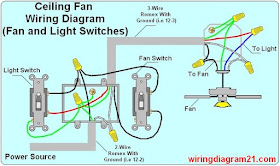
The line voltage enters the switch outlet box and the hot wire will connect to every switch. Switch hots and line neutral will connect to a 3-wire-cable that travels to the fan/light outlet box in the ceiling. The light kit will switch to the red wire of the 3-way cable and the fan control switch will connect to the black wire. 
In this diagram, the black wire of the ceiling wire is for the fan and the blue wire is for the light kit.

ceiling fan wiring diagram double switch fan and with light switch how teo wire a ceiling fan how to install

With the diagrams listed above, you can wire a ceiling fan with either a single switch or double switch.

Dimmer switch and fan speed wiring diagram :

ceiling fan dimmer switch light kit wiring diagram

Dimmer switch and speed controller wiring diagram :

ceiling fan dimmer switch spped controller wiring diagram

Sunday, October 23, 2016

RJ45 Wiring Diagram Ethernet Cable


This article shows how to wire an Ethernet jack RJ45 wiring diagram for a home network with color code cable instructions and photos.and the difference between each type of cabling crossover, straight through

Ethernet is a computer network technology standard for LAN (Local area network). It was introduced commercially in 1989 and became IEEE Standard 802.3 in 1983. It has good backward compatibility and it runs at 10Mb, 100Mb or 1Gb per second. It can use a star topology (standard UTP cable) or a bus (old coaxial cable).


What is RJ45?

RJ45 connectors also known as 8P8C - (ISO 8877) are a kind of Unshielded Twisted Pair cables (UTP).

Ethernet Cable UTP RJ45 Wiring Diagram


There are two standards that are used for RJ45 connector wiring. They are EIA/TIA 568A and EIA/TIA 568B. They can also be known as T-568A and T-568B. Both standards can be used to make Ethernet UTP network cable. The cable could be a straight-through cable or a cross-over cable
             

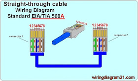
RJ45 WIRING DIAGRAM OF EIA/TIA 568A ETHERNET CABLE


rj45 ethernet patch cable wiring diagram straight trought  568 a

 Color codes of straight through  standard TIA/EIA 568 A :

  • Pin 1 is White Green 
  • Pin 2 is Green
  • Pin 3 is White orange
  • Pin 4 is Blue
  • Pin 5 is White Blue
  • Pin 6 is Orange
  • Pin 7 is White Brown 
  • Pin 8 is Brown 

Pin Functionalities :

  • Pin 1 is “TX+_D1” or Transmit Data+
  • Pin 2 is “TX-_D1” or Transmit Data-
  • Pin 3 is “RX+_D2” or Receive Data+
  • Pin 4 is “BI+_D3” or Bi-directional+
  • Pin 5 is “BI-_D3” or Bi-directional-
  • Pin 6 is “RX-_D2” or Receive Data-
  • Pin 7 is “BI+_D4” or Bi-directional+
  • Pin 8 is “BI-_D4” or Bi-directional-

RJ45 WIRING DIAGRAM OF EIA/TIA 568B ETHERNET CABLE 


The pin description and names are the same as that for EIA/TIA 568A Ethernet cable. But the position of the different colored wires varies for both.
For optimal performance, a single cable has to be used for pins 1 and 2, pins 3 and 6, pins 4 and 5 and pins 7 and 8.

rj45 ethernet patch  straight through cable wiring diagram  568 b color code


Look here for a Straight cable color code standard TIA/EIA 568 B :

  • Pin 1 is White orange   
  • Pin 2 is Orange  
  • Pin 3 is White Green  
  • Pin 4 is Blue
  • Pin 5 is White Blue
  • Pin 6 is Green
  • Pin 7 is White Brown 
  • Pin 8 is Brown 

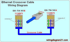
RJ45 WIRING DIAGRAM OF ETHERNET CROSSOVER CABLE 

A crossover cable contains a 568A specification at one end and a 568B specification at the other end.

rj45 ethernet crossover cable wiring diagram color code

Look for here a Crossover cable color code :

    
             Connector 1                                                                               Connector 2
  • Pin 1 is White orange  ------------------------------------------->  Pin 1 is White Green 
  • Pin 2 is Orange            ------------------------------------------->  Pin 2 is Green
  • Pin 3 is White Green   ------------------------------------------->  Pin 3 is White orange
  • Pin 4 is Blue                --------------------------------------------> Pin 4 is Blue
  • Pin 5 is White Blue     --------------------------------------------> Pin 5 is White Blue
  • Pin 6 is Green             -------------------------------------------->  Pin 6 is Orange
  • Pin 7 is White Brown ---------------------------------------------> Pin 7 is White Brown 
  • Pin 8 is Brown            -------------------------------------------->  Pin 8 is Brown


RJ45 WIRING DIAGRAM

                         CLICK HERE >>>  RJ45 WIRING DIAGRAM
 

How To Crimp  Rj45 cable :


Items needed to wire an Ethernet cable  

  • Crimper
  • RJ 45 Connectors
  • Bulk Cable
  • Cable Tester
  • Wire cutter

Steps for rj45 wire diagram an Ethernet cable


  1. Roll off the cable to the desired length plus a little extra and cut it.
  2. Strip the outer jacket of the cable using a stripper or a knife. You can strip of about 3 cm length. There are 8 wires that are twisted in 4 pairs. Each pair of wire has a wire of a distinct color. There will be another wire that is striped with the matching color of its partner. This wire is known as a tracer.
  3. Check the wires for any cut that is exposing the copper wire inside. If there is any like that, you might need to cut the wire and start again. If copper wire is exposed, it could lead to poor performance or crosstalk.
  4. Untwist the pairs of wires and align them in the right order. You should refer to the diagram above to check the proper color orientation for each wiring standard. For a crossover cable (rj45 wiring diagram ), one end is EIA/TIA 568B and the other end is EIA/TIA 568A.
  5. Keep the end of the wires flat and trim their ends leaving about 12.5 mm in length. Insert the wires into the RJ-45 plug while holding the connector or clip down. Ensure each wire is pushed deep and examine the connection again to confirm the arrangement.
  6. Hold the wire and place the plug into the crimping tool. You can also double crimp to ensure that the pins are properly set.
  7. All the steps above should be repeated for the other end of the cable.
  8. Now the Ethernet cable should be tested. You can test the connectivity from pin to pin or use a network cable tester. 
Helpful Tips & Hints
  • If the Ethernet cable does not work, check that the pins of both ends are connected. You can cut off the connector and repeat the steps above if not. Ensure that the connector is tightly crimped.
  • The network cable length segment could be as long as 100m or even 150m in some cases. ‘
  • Cat 5e cable is now the standard used instead of the Cat 5 standard. Cat 5e allows for longer distances and allows for far end crosstalk and better quality.
  • For long cables, ensure that you test the cable before running it as this would save you a lot of stress. 
  • Ethernet cables should not be bent, stapled, stretched or deformed in any manner. Do not run them near noise inducing components and do not run them parallel with power cables.
Are You Interested in the article :


Friday, September 9, 2016

4 Way Switch Wiring Diagram


look for 4 way switch wiring diagram or step how to wire a four way light switch electrical circuit
A 4 way switch is a double pole double throw (DPDT) switch. It has 4 terminals or poles and consists of two 3-way switches that are modified. The switch can be used to control the electricity supplying lights from three locations. All four terminals are always brass in color. Traveler wires receive and transfer the electricity from each of the two 3 way switches.
A 4-way switch can be used in scenarios where you need to control the lighting of a particular place from 3 points. For example, you could have switches at each end of a hallway and a switch halfway down the hallway. You could also have switches at the top & bottom of a stairway and a switch by the front door.
One important factor to always remember is that you can’t have a 4-way switch without two 3-way switches.
Directions:
Note: The diagrams below are shown using the Type NM Cable wiring option. These cables always have ground/earth conductor with them. The earth conductor is very necessary for insuring that the ground path is solid and will not fail. When making use of metal boxes, the earth conductor should always be attached to each metal box with the use of a threaded ground screw or the use of other means of attachment. The frames of all switches must also be attached to the earth conductor. Fixture boxes and switch boxes are not shown but they are necessary. 4 way switch wiring diagram how to wire for way

DANGER: The mains must always be turned off before any work is started.  To avoid electrocution, the supply to the circuit must be dead. Turn the power off yourself and use a tester screwdriver to be extra sure. To be forewarned is to be forearmed. One can’t be too careful when it comes to working with electricity.

The two methods for wiring a 4 way switch are shown below:
  • 4 way switch wiring diagram with the power feed through a switch:  

4 way switch wiring diagram how to wire double pole switche                                                                                                                                 
       In this circuit, the power comes in through the first switch. The hot is connected to the common on the switch and the neutral is spliced to all the switch boxes through the neutral terminal of the light.  The switches connecting the travelers are connected with a three wire cable. A 2-wire cable is used for the purpose of connecting the last switch to the light fixture. The common on the last switch is connected to the hot terminal of the light fixture.


  •  4 way switch wiring diagram with the power feed through the light :


  • 4 way light switch wiring diagram how to wire double pole switche

              In this method the power source is at the light fixture and the two 3-way switches follow after the light fixture.
              A 2-wire cable is connected from the light fixture to the first 3-way switch. The hot source is connected to the common on the first switch and the hot terminal on the light is spliced through all the light fixtures to the common of the last switch.
    Here the traveler run from the first switch to a set of terminals on the 4-way switch and from the second switch to the travelers on the last 3-way switch. The source of the hot to the light is the common terminal which is spliced through each switch box.

     4 way switch wiring diagram with multiple lights power source feed vea the switch :


     4 way switch wiring diagram with multiple lights power source feed vea the switch

     4 way switch wiring diagram with multiple lights power source feed vea the light :


     4 way switch wiring diagram with multiple lights power source feed vea the switch


    Are You Interested in article :


    Saturday, June 11, 2016

    3 Way Switch Wiring Diagram


    This article explains a 3 way switch wiring diagram and step How to wire three way light switch electrical circuit We have to discuss about what are the three ways for wiring diagram as discussed below and how to connect all the lights and what are the different techniques to join such switches to getour own desired outputs as mentioned below. We will also develop kind of topics as multiple switching and single switching connections for connecting light switches as three way switching and wirings.

    To give you an understanding how to connect this complicated switch as by three ways called three way light switches. Also showing by the help of pictures to clarify the correct connection of the switch that helps to light up huge halls or long streets at only one touch as one or two switches connected to each other controlling the whole scenario.


     Important Cautionary Note! You want to make sure that you are being safe and that means that you need to turn off the power to the circuit that you are working on. You want to make sure that you are working with a tester and that you also check this as well on your own.

    1.  3 Way Switch Wiring Diagram with Power Feed Via Switch :                                                                                                                                                                                                   how to wire a 3 way light switch wiring diagram electrical circuit
                                                                        

    1.                                                                                                                       You will see what you need to do when the power is coming to the light switch. The power source also connects the terminal main three-way switch and means that you need to have it spliced with a 3 way switch with the wire cable and that you will see the way that there is a neutral terminal with the light. When the hot is connected from the terminal to the hot of the light you will have completed this correctly.                                                                                                                                                                                                                              

    1. 3 Way Switch Wiring Diagram with Power Feed Via Light :


    how to wire a 3 way light switch wiring diagram electrical circuit

    Now discussing 3-way light switch wiring diagram as also discussed above the color codes of the wires as having three insulated conductors as black as hot, red as switch wire or called traveler and white as common wire as also shown when light is connected to both black and white wires. The main difference between the ‘figure A’ and ‘Figure B’ are that ‘Figure A’ didn’t involve power source to the light while Figure B involve power source. Using wire nuts to attach green wires together that it’s important for connecting 3-way switch for lightening a bulb or light as also shown in diagram above. As you observe we have four type of wires here having yellow cap with green wires to cover the short circuiting if any fault occurs. The most common way to wire a 3-way switch while want to light-up of your staircase or hallway. Light switch at one end, lights in the middle, light switch at the other end and its simple. Trace the wires carefully in the diagram so you can connect them to the proper locations. Also choose (12-3) 3-wire Romex with ground for short-circuit safety from 3-way switch that we have to cover all aspects for our own safety.


    3 way light switch wiring diagram poower source feed via light :


    3 way switch wiring diagram how to wire a light switch


    First you have to turn off the correct electrical panel circuit by adding this electrical box for the three-way switch in that place or called basement. You have also to make space for the three way switch because of many wires then single switch. While also showing above in the circuit having three insulated conductors as black as hot, red as switch wire or called traveler and white as common wire as also shown when light is connected to both black and white wires. Having length of 14-3 type NM cable (or 12-3, if you’re connecting to 12-gauge wire) between the two boxes as shown in the figure above named as 3 wire ROMEX with ground*(12-3). Connecting these wires to the new three-way switches with ground as shown above. Be sure to wrap black or yellow as shown above an electrical tape around the ends of all white wires that are used as travelers between the three-way switches. If you have the setup shown in Fig. A, also wrap black tape around the white wire from the switch to the light. This way, both you and others will know these wires are “hot” and not neutral like most white wires.


    Two lights between 3 way switches wiring diagram (power source feed via a light ) :


    3 way switch wiring diagram  multiple light double how to wir a double light


    There the scenario is changed we have to connect two lights using two 3-Way switch mechanisms we have to just add one more light in between the first light and one of the 3-way switch. Follow the wire colors to connect them easily or electrician will be better for making the circuit more easily.


    3 way swith with  multiple light wiring diagram with power source feed via light switch :


    3 way switch wiring diagram  multiple light double howto wire a light switch

    Actually the diagram explains everything clearly while controlling by two 3-way switches with a two wire cable power supply as shown. Remember only two wire cable with ground is necessary for the boxes at the lights we see there. Traveller wires (red in color) connect the three-way switches without going in deep to the system or circuit given. 


    Are You Interested in article :