This article shows 4 ,7 pin trailer wiring diagram connector and step how to wire a trailer harness with color code ,there are some intricacies involved in wiring a trailer. Some trailers come with different connectors for cars and some have different wiring styles. If you follow our trailer wiring diagrams, you will get it right. Some connectors are 4-pin while some are 7-pin.
4 pin trailer light wiring diagram :
4-Pin Connectors4-pin connectors are the standard used for most trailers. Many trailers have three circuits. The circuits are for left and right brake lights and running lights. Three wires are for the trailer while the last wire is the ground wire. The ground wire should be run from the frame of the vehicle to the trailer. There must be a very consistent metal to metal contact for the ground wire. So, do not run the wire from the bumper or the hitch of the car. The 4-pin standard flat style connector has four contacts with a male pin on the vehicle side for the ground.
Wiring the 4-pin connector
You will need a volt meter and a cutting plier to splice the wires. Turn on the running lamps of your vehicle. Probe the wiring to determine which of the wire that leads to the taillight is for the running lamp. Splice this wire and bring it to the vehicle end of the connector. The connection diagram below will tell you the exact place to place the wire. Repeat the process above for the left turn signal and the right turn signal lights
Thir is standard color code for a trailer light 4 wire :
- Brown wire: Tail light and marker light
- Green wire : Right Turn Signal
- Yellow wire: Lift Turn Signal
- White wire : Trailer Ground
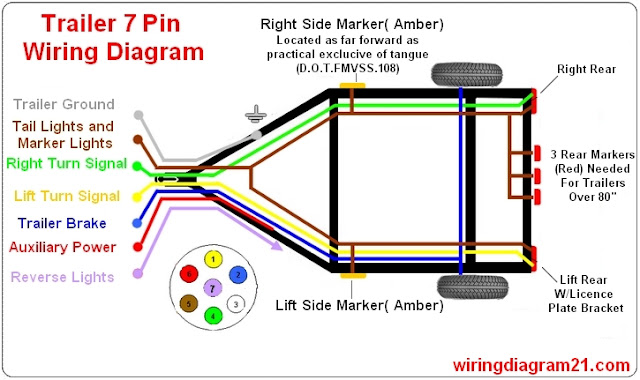
7 pin trailer light wiring diagram :
7-Pin Connectors
7-pin connectors are needed because some trailers need extra connections due to the fact that they have multiple circuits. There are pins for electric trailer brakes, auxiliary power and reverse lights.
Thir is standard color code for a trailer light 7wire
Extra Notes
- White wire : Trailer Ground
- Brown wire: Tail light and marker light
- Green wire : Right Turn Signal
- Yellow wire: Lift Turn Signal
- Blue wire : Trailer Brake
- red wire : Auxiliary Power
Extra Notes
- It is good to smear some dielectric grease on the connectors so that the pins will not be corroded by moisture.
- Ensure everything is properly tightened and fixed so you do not have a loose connection. It will also save you the stress of troubleshooting later on.
- 3 Way Switch Wiring Diagram
- 2 Way Switch Wiring Diagram
- 4 way Switch Wiring Diagram
- RJ45 wiring Diagram


